How to add a custom board definition to a Zephyr application
Guest author Chris Wilson explains how a Golioth training inspired him to dig into how to add a new board definition in Zephyr
from Chris Gammell announcing a that Golioth would be offering the following month. At the time, I had no previous experience working with Zephyr or the Golioth IoT platform, but this seemed like a good introduction to both–so I signed up!
The training offered by the Golioth team was really approachable, even for people like me without an extensive background in firmware development or real-time operating systems. The training starts with a basic introduction to building firmware in the underlying and progresses through a series of examples that showcase the features of the .
However, there was one aspect of the training that initially confused me: the instruct you to build firmware for the board, but then run that firmware image on the
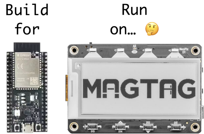
application, the -b esp32s2_saola board argument is passed to the west build command:
west build -b esp32s2_saola app/golioth-demo
Why are we building firmware for a completely different board? 🤔
It turns out this works because:
This highlights one of the strengths of the underlying Zephyr RTOS: the ability to quickly extend or modify existing board definitions through the use of devicetree overlay files. Overlays make it possible to extend or modify an existing board definition to support new hardware variants, without having to go through the major effort of defining and upstreaming a brand new board definition to the Zephyr project.
This is great for getting something running quickly, but since these are totally different boards, I thought it felt a bit awkward (and potentially confusing) to keep using the esp32s2_saola board name in the training demos. I thought:
Wouldn’t it be nice if we could use the
adafruit_magtagboard name in the Golioth demo apps without having to add it to the upstream Zephyr repo?
Fortunately, Zephyr’s flexibility provides us with an option: we can bundle a custom MagTag board definition alongside the training demo apps, without having to touch the upstream Zephyr repository!
In this article, I’ll walk through step-by-step how I for the Adafruit MagTag board in the Golioth repository. By the end of the article, we’ll be able to pass the adafruit_magtag board argument to west commands like this:
west build -b adafruit_magtag app/golioth-demo
Since we want to add support for a new physical board, we need to understand what a “Board” is in the Zephyr ecosystem.
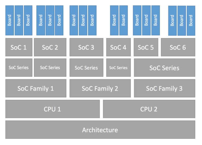
this way:
A target system with a defined set of devices and capabilities, which can load and execute an application image. It may be an actual hardware system or a simulated system running under QEMU. The Zephyr kernel supports a .
Zephyr already has support for the Xtensa CPU (zephyr/arch/xtensa/core/) and the ESP32-S2 SoC (zephyr/soc/xtensa/esp32s2/), so we don’t need to add anything new for these layers. The only thing we need to add is a new definition for the MagTag board itself.
Let’s dig into the Zephyr documentation to see how to add support for a new board.
Adding a new Board in Zephyr
Zephyr has extensive documentation on how to add support for new hardware (see ). For this article specifically, I referred to the that covers how to add support for a new board in Zephyr.
Zephyr is flexible and it supports pulling in board definitions from multiple possible locations. Before we can dive in and start adding a new MagTag board definition, we need to understand where to locate the files so the Zephyr build system can find them. To do that, we need to take a quick step back to understand how west workspaces and manifest repositories work.
Understanding west workspaces and manifest repositories
Building a Zephyr-based firmware image requires pulling in source code for the bootloader, kernel, libraries, and application logic from multiple Git repositories (the Zephyr term for these individual Git repositories is projects). Managing these individual repos manually would be a nightmare! Thankfully, Zephyr provides a command line tool named west that automatically manages these Git repositories for us.
West manages all these dependencies inside a top-level directory called a workspace. Every west workspace contains exactly one manifest repository, which is a Git repository containing a manifest file. The manifest file (named west.yml by default) defines the Git repositories (projects) to be managed by west in the workspace.
West is flexible and supports multiple topologies for application development within a workspace (you can read about all the supported topologies ). The magtag-demo repo is structured as a variation of the . This means the magtag-demo repo is the manifest repository inside the magtag-demo-workspace west workspace, and the repository is included as a dependency in the west manifest file (in our example we keep this in deps/zephyr).
The workspace looks something like this (some folders redacted for clarity):
magtag-demo-workspace/                 # west workspace ("topdir")
├── .west/                             # marks the location of the west topdir
│   └── config                         # per-workspace local west configuration file
│
│   # The manifest repository, never modified by west after creation:
├── app/                               # magtag-demo.git repo cloned here as "app" by west
│   ├── golioth-demo/                  # Zephyr app for Golioth demo
│   │   └── boards/
│   │       ├── esp32s2_saola.conf     # app-specific software configuration
│   │       └── esp32s2_saola.overlay  # app-specific hardware configuration
│   └── west.yml                       # west manifest file
│
│   # Directories containing dependencies (git repos) managed by west:
└── deps/
    ├── bootloader/
    ├── modules/
    ├── tools/
    └── zephyr/
        └── boards/
            └── xtensa/
                └── esp32s2_saola/     # board definition for ESP32-S2-Saola-1
When we run the west build -b esp32s2_saola command, the Zephyr build system will look for a board named esp32s2_saola in a subdirectory of the zephyr/boards directory AND in a subdirectory of app/boards (if it exists). As you can see in the hierarchy above, the zephyr repo already includes the board definition for the ESP32-S2-Saola-1 board in the zephyr/boards/xtensa/esp32s2_saola/ directory, so this is the board definition that is pulled in when building the golioth-demo application.
However, if you look in the magtag-demo-workspace/app/golioth-demo/boards/ directory, you’ll notice files like esp32s2_saola.conf and esp32s2_saola.overlay that extend the esp32s2_saola board definition to enable additional software/hardware features on the MagTag board (LEDs, buttons, etc). I’ll cover the details of these files later on in this article, but for now, you just need to know that they allow application-specific modifications to the base esp32s2_saola board definition. The key takeaway here is that your Zephyr application can use and extend any existing board definition from the upstream zephyr repo.
So, to recap, if we want to add a new adafruit_magtag board definition for our app, there are two places where we could add it:
zephyr repository as boards/xtensa/adafruit_magtagmagtag-demo repository as boards/xtensa/adafruit_magtagIf we add the board definition into the upstream zephyr repository, it would make the board definition available to anybody who uses Zephyr. That’s great! However, it can take a while for the Zephyr developers to review and approve a PR to add a new board definition. It is also for the board as part of the PR, which adds some additional overhead to the submission process.
In this article, we’re just going to add the custom board definition in the magtag-demo repo (as described ) so that we can bundle it alongside the training apps without waiting for it to go through the upstream submission process.
By the end of this article, we’ll end up creating the following new files:
magtag-demo-workspace/
└── app/
    ├── boards/
    │   └── xtensa/
    │       ├── Kconfig.board
    │       ├── Kconfig.defconfig
    │       ├── adafruit_magtag-pinctrl.dtsi
    │       ├── adafruit_magtag.dts
    │       ├── adafruit_magtag_defconfig
    │       └── board.cmake
    ├── dts/
    │   └── bindings/
    │       └── gpios.yaml
    ├── golioth-demo/
    │   └── boards/
    │       ├── adafruit_magtag.conf
    │       └── adafruit_magtag.overlay
    └── zephyr/
└── module.ymlCreate the new board directory
The first step is to create a new directory where we can add the files for the adafruit_magtag board definition:
magtag-demo-workspace/app/boards/xtensa/adafruit-magtag/
west boards to get a list of the existing Zephyr board names.
to describe the hardware available on supported boards. Using devicetree, many aspects of the hardware can be described in a data structure that is passed to the operating system at boot time. Using this data structure, the firmware can get information about the underlying hardware through the standard devicetree.h API at runtime.
The devicetree data structure is essentially a hierarchy of nodes and properties. In practice, the hierarchy of nodes reflects the real-world hierarchy of the hardware, and the properties describe or configure the hardware each node represents.
There are four Devicetree files we need to provide as part of the board definition:
magtag-demo-workspace/
└── app/
    ├── boards/
    │   └── xtensa/
    │       ├── adafruit_magtag-pinctrl.dtsi
    │       └── adafruit_magtag.dts
    ├── dts/
    │   └── bindings/
    │       └── gpios.yaml
    └── golioth-demo/
        └── boards/
            └── adafruit_magtag.overlay
adafruit_magtag-pinctrl.dtsi
Zephyr uses a system called to map peripheral functions (UART, I2C, etc) to a specific set of pins. It’s common to put these pin definitions in a
The Golioth uses UART0 for the serial console, I2C1 for the onboard LIS3DH accelerometer, SPIM2 for the WS2812 “neopixel” LEDs, and LEDC0 as the PWM controller for the red LED.
Here’s the pin mapping for these peripherals on the MagTag board:
UART0:
TX: GPIO43RX: GPIO44I2C1:
SDA: GPIO33SCL: GPIO34SPIM2
MOSI: GPIO1MISO: (not used)SCLK: (not used)To describe the hardware pin mapping, we need to create a devicetree include file:
magtag-demo-workspace/app/boards/xtensa/adafruit-magtag/adafruit_magtag-pinctrl.dtsi
First, we need to include a couple pin control header files for the ESP32-S2. These files contain macros that we’ll use in the pin control definitions:
#include#include #include
/include/ "" syntax for including other files, the C preprocessor is run on all devicetree files, so includes are generally done with C-style #include instead.Espressif also provides an ESP32-S2 devicetree include file (zephyr/dts/xtensa/espressif/esp32s2.dtsi) that contains a devicetree node for the pin controller called pin-controller with a node label named pinctrl:
pinctrl: pin-controller {
    compatible = "espressif,esp32-pinctrl";
    status = "okay";
};
We need to extend this node to include the missing pin configuration for the MagTag board. Zephyr provides a convenient shortcut to refer to existing devicetree nodes via the &node syntax (where node is the node label). In the adafruit_magtag-pinctrl.dtsi file, we’ll refer to this node as &pinctrl and extend it by providing additional properties:
&pinctrl {
    ...
};
Pin control has the concept of , which can be used to set different pin configurations based on runtime operating conditions. Currently, two standard states are defined in Zephyr: default and sleep. For the Golioth magtag-demo we’re only going to define pin mappings for the default state.
Let’s define the default state mapping for the UART0 pins. We’ll define a node named uart0_default with matching node label uart0_default. Since the RX pin requires an internal pull-up to be enabled on our board, we’ll define two groups: group1 and group2. Groups allow properties to be applied to multiple pins at once, and we’ll use it here to apply the bias-pull-up property to the RX pin. In each group, pins are declared by assigning one of the macro definitions from esp32s2-pinctrl.h to the pinmux property. For example, the UART0_TX_GPIO43 macro assigns GPIO43 to the UART0 peripheral as TX, and UART0_RX_GPIO44 assigns GPIO44 to the UART0 peripheral as RX:
&pinctrl {

    uart0_default: uart0_default {
        group1 {
            pinmux = ;
        };
        group2 {
            pinmux = ;
            bias-pull-up;
        };
    };

};
We can follow the same procedure to define additional pin mappings for the I2C1, SPIM2, and LEDC0 peripherals (you can see the complete pin control mapping file here).
Now that we’ve got the pin control mappings defined, we can use them in the main adafruit_magtag.dts devicetree source file.
adafruit_magtag.dts
To describe the hardware available on the board, we need to create a devicetree source (DTS) file:
magtag-demo-workspace/app/boards/xtensa/adafruit-magtag/adafruit_magtag.dts
First, we add a line specifying the devicetree syntax version we’re going to be using in the file:
/dts-v1/;
Next, we include the ESP32-S2 SoC devicetree definitions provided by Espressif in zephyr/dts/xtensa/espressif/esp32s2.dtsi:
#include
This file defines the hardware available on the ESP32-S2 SoC such as the available CPUs, flash memory, WiFi, GPIOs, etc.
status = "disabled";). We’ll enable all the peripherals used on the MagTag board later.Since the MagTag board has a PWM-capable LED, we also need to include the PWM device tree bindings header file so that we can use the PWM_HZ(x) macro:
#includeFinally we include the file we created earlier which defines the pin control mappings for the board:
#include "adafruit_magtag-pinctrl.dtsi"Now we can define the actual device tree data structure for the MagTag board.
/defines the root for the board. Themodeldefines a human readable name for the board, and thecompatibleproperty can be used to match this node to a compatible file (you can think of bindings as a sort of schema for the nodes):/ { model = "adafruit_magtag"; compatible = "adafruit,magtag"; ...First, we’ll create a node for the GPIO-controlled LEDs on the MagTag board.
The LEDs on the MagTag board are connected to GPIO pins on the ESP32-S2, so we’ll look in the to see if there is already a binding that describes this hardware feature. There’s one called and the description says:
This allows you to define a group of LEDs. Each LED in the group is controlled by a GPIO. Each LED is defined in a child node of the gpio-leds node.
Perfect! That sounds exactly like what we want.
We’ll create a
ledsnode for the MagTag based on the example provided in the binding file. Thecompatibleproperty says that this node is compatible with thegpio-ledsbinding. Each individual LED is defined as a child node underleds. For example,led_0is defined as pin13ongpio0, and is assigned the node labelred_led. TheGPIO_ACTIVE_HIGHflag means the LED is on when the pin is high, and off when the pin is low.leds { compatible = "gpio-leds"; red_led: led_0 { gpios = <&gpio0 13 GPIO_ACTIVE_HIGH>; }; };Right about now, you might be scratching your head wondering how the heck we knew what to put in the value for the
gpiosproperty (i.e.<&gpio0 13 GPIO_ACTIVE_HIGH>;).Here’s how you figure it out:
The
gpio-leds.yamlfile defines thegpiosproperty astype: phandle-array, so we know that the value for this property must be of the form<&phandle specifier1 specifier2 etc...>. We also know that the MagTag board has a RED LED connected to pin 13 of theGPIO0controller, so we need to use the&gpio0phandle to refer to the controller node. Let’s look up thegpio0controller inzephyr/dts/xtensa/espressif/esp32s2.dtsi:gpio0: gpio@3f404000 { compatible = "espressif,esp32-gpio"; gpio-controller; #gpio-cells = <2>; reg = <0x3f404000 0x800>; interrupts =; interrupt-parent = <&intc>; ngpios = <32>; /* 0..31 */ }; The
#gpio-cells = <2>;property tells us that there are two specifiers required for the&gpio0phandle. Thecompatible = "espressif,esp32-gpio";property tells us the name of the binding that defines what those specifiers should be. Looking inzephyr/dts/bindings/pwm/espressif,esp32-ledc.yaml, it defines the specifiers required forgpio-cells:gpio-cells: - pin - flagsPutting it all together, we can see that the property must be specified like this:
gpios = <&gpioX pin flags>;which in this specific example is:
gpios = <&gpio0 13 GPIO_ACTIVE_HIGH>We can follow the same procedure to define additional nodes for the PWM LEDs and the buttons on the MagTag (using the
pwm-ledsandgpio-keysbindings respectively). You can see these nodes in the complete device tree source file here.The MagTag board has a couple other GPIOs that are used to gate the neopixel power, control the ePaper display, and drive the speaker. Unfortunately, there aren’t any existing Zephyr bindings we can use to expose this hardware to the custom drivers in the
magtag-demorepo, so we’ll create a simplegpios.yamlbinding file that allows us to define groups of GPIOs:magtag-demo-workspace/app/dts/bindings/gpios.yamlThe binding defines a single
gpiosproperty (similar togpio-ledsandgpio-keys):description: | This allows you to define a group of GPIOs. Each GPIO is defined in a child node of the gpios node. Here is an example which defines three GPIOs in the node /brd-ctrl: / { brd-ctrl { compatible = "gpios"; ctrl_0 { gpios = <&gpio0 1 GPIO_ACTIVE_LOW>; }; ctrl_1 { gpios = <&gpio0 2 GPIO_ACTIVE_HIGH>; }; ctrl_2 { gpios = <&gpio1 15 (GPIO_PULL_UP | GPIO_ACTIVE_LOW)>; }; }; }; compatible: "gpios" child-binding: description: GPIO child node properties: gpios: type: phandle-array required: trueNow that we have a generic
gpiosbinding, we can add the missing nodes for the remaining GPIOs.Let’s create a
speakernode that contains the GPIOs needed for the speaker on the MagTag board. In the same way we defined the LEDs above, we define two GPIOs,activeto enable the speaker andsoundto drive the speaker:speaker { compatible = "gpios"; active: active_pin { gpios = <&gpio0 16 GPIO_ACTIVE_HIGH>; }; sound: sound_pin { gpios = <&gpio0 17 GPIO_ACTIVE_HIGH>; }; };We can follow the same procedure to define additional nodes for the neopixel power and the e-paper display GPIOs (you can see these nodes in the complete device tree source file here).
Finally, we’ll create the
/aliasand/chosennodes.The
/chosennode is used to define a set of commonly used Zephyr properties for system-wide settings like the UART device used by console driver, or the default display controller. These properties refer to other nodes using their phandles (&node, wherenodeis the node label):chosen { zephyr,sram = &sram0; zephyr,console = &uart0; zephyr,shell-uart = &uart0; zephyr,flash = &flash0; };The
/aliasesnode is used to override generic hardware devices defined by an application. For example, the sample application requires an aliasled0to be defined. We can build and run the Blinky app on any board that defines this alias, including the MagTag board which defines the aliasled0 = &red_led;to mapled0to the red LED:aliases { watchdog0 = &wdt0; led0 = &red_led; pwm-led0 = &red_pwm_led; led-strip = &led_strip; sw0 = &button0; sw1 = &button1; sw2 = &button2; sw3 = &button3; neopower = &neopower; mosi = &mosi; sclk = &sclk; csel = &csel; busy = &busy; dc = &dc; rst = &rst; activate = &active; sound = &sound; };Now that we’ve finished creating new child nodes under the root node, we can start to customize the existing SoC nodes we included from
espressif/esp32s2.dtsi. This is required to provide board-specific customizations, such configuring the pins used for a SPI peripheral or specifying the devices present on an I2C bus. As I mentioned earlier, Zephyr provides a convenient shortcut to refer to existing nodes via the&nodesyntax (wherenodeis the node label) so we don’t need to write out the full device tree path.Let’s start by taking a look at the
I2C1controller node that is defined inzephyr/dts/xtensa/espressif/esp32s2.dtsi:i2c1: i2c@3f427000 { compatible = "espressif,esp32-i2c"; #address-cells = <1>; #size-cells = <0>; reg = <0x3f427000 0x1000>; interrupts =; interrupt-parent = <&intc>; clocks = <&rtc ESP32_I2C1_MODULE>; status = "disabled"; }; We can see that the
I2C1controller is disabled by default (status = "disabled";) and it’s missing some of the properties required by theespressif,esp32-i2cbinding (for example, the pinctrl properties). In ouradafruit_magtag.dtsfile, we can refer to the&i2c1node and define the missing required properties:&i2c1 { ... };The
pinctrl-*properties assign thei2c1_defaultpin control state to the controller and give it the name"default". To enable the theI2C1controller, we override thestatusproperty by assigningstatus = "okay";. We also set the I2C clock frequency toI2C_BITRATE_STANDARD(100 Kbit/s).&i2c1 { pinctrl-0 = <&i2c1_default>; pinctrl-names = "default"; status = "okay"; clock-frequency =; }; The MagTag board has an onboard
LIS3DHaccelerometer on theI2C1bus, so we also add a subnodelis3dh@19. In devicetree jargon, the@19is called the unit address and it defines the “subnode’s address in the address space of its parent node” (which in this case is the accelerometer’s I2C address in the address space of possible I2C addresses). Thecompatible = "st,lis2dh";property assigns the correct binding for the accelerometer so that the Zephyr sensor drivers can use it, and thereg = <0x19>;property sets the device’s I2C address on the bus.&i2c1 { pinctrl-0 = <&i2c1_default>; pinctrl-names = "default"; status = "okay"; clock-frequency =; lis3dh@19 { compatible = "st,lis2dh"; reg = <0x19>; }; }; Some nodes, like
&gpio0, don’t require any additional configuration, but are disabled by default. These nodes can be enabled simply by overriding thestatusproperty:&gpio0 { status = "okay"; };We can follow the same procedure to configure the remaining nodes for the ESP32-S2 SoC (you can see these nodes in the complete device tree source file here).
adafruit_magtag.overlayIn some cases, an application may need to extend or modify nodes in the board’s devicetree structure. Zephyr provides this flexibility through the use of a devicetree file. The build system will automatically pick up the overlay file if it’s placed in the
subdirectory and named/boards/ ..overlay For example, let’s create an overlay for the
golioth-demoapp in themagtag-demorepo:magtag-demo-workspace/app/golioth-demo/boards/adafruit_magtag.overlayThe
&wifinode for the ESP32-S2 is disabled by default. Thegolioth-demoapp needs Wi-Fi to be enabled so it can connect to the Golioth cloud, so we’ll enable it in the app overlay:&wifi { status = "okay"; };You can see the complete overlay file here
to specify these configuration options.
For more details on how to use Kconfig to configure the Zephyr kernel and subsystems, see in the Zephyr docs.
There are four Kconfig files we need to provide as part of the board definition:
magtag-demo-workspace/ └── app/ ├── boards/ │ └── xtensa/ │ └── adafruit-magtag/ │ ├── Kconfig.board │ ├── Kconfig.defconfig │ └── adafruit_magtag_defconfig └── golioth-demo/ └── boards/ └── adafruit_magtag.conf
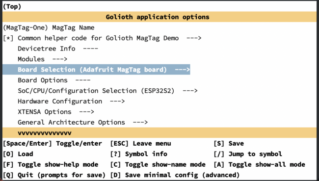
Kconfig.boardThis file is included by to include your board in the list of available boards. We need to add a definition for the top-level
BOARD_ADAFRUIT_MAGTAGKconfig option. Note that this option should depend on theSOC_ESP32S2Kconfig option which is defined insoc/xtensa/esp32s2/Kconfig.soc:config BOARD_ADAFRUIT_MAGTAG bool "Adafruit MagTag board" depends on SOC_ESP32S2
Kconfig.defconfigThis file sets board-specific default values.
# Always set CONFIG_BOARD here. This isn't meant to be customized, # but is set as a "default" due to Kconfig language restrictions. config BOARD default "adafruit_magtag" depends on BOARD_ADAFRUIT_MAGTAGThe
ENTROPY_GENERATORKconfig option enables the entropy drivers for the networking stack:config ENTROPY_GENERATOR default y
adafruit_magtag_defconfigThis file is a Kconfig fragment that is merged as-is into the final
.configin the build directory whenever an application is compiled for this board.The
CONFIG_XTENSA_RESET_VECTORKconfig option controls whether the initial reset vector code is built. On the ESP32-S2, the reset vector code is located in the mask ROM of the chip and cannot be modified, so this option is disabled:CONFIG_XTENSA_RESET_VECTOR=nWhenever we’re building an application for this board specifically, we want to ensure that the top-level Kconfig options for the SoC and the board itself are enabled:
CONFIG_BOARD_ADAFRUIT_MAGTAG=y CONFIG_SOC_ESP32S2=yChange the main stack size for the various system threads to
2048(the default is1024):CONFIG_MAIN_STACK_SIZE=2048Set the system clock frequency to 240 MHz:
CONFIG_SYS_CLOCK_HW_CYCLES_PER_SEC=240000000Zephyr is flexible and it supports emitting console messages to a wide variety of console “devices” beyond just a serial port. For example, it is possible to emit console messages to a RAM buffer, the semihosting console, the Segger RTT console, etc. As a result, we need to configure Zephyr to:
Enable the console drivers ( CONFIG_CONSOLE)Enable the serial drivers ( CONFIG_SERIAL)Use UART for console ( CONFIG_UART_CONSOLE)CONFIG_CONSOLE=y CONFIG_SERIAL=y CONFIG_UART_CONSOLE=yThe ESP32-S2 defines its own
__startso we need to disableCONFIG_XTENSA_USE_CORE_CRT1:CONFIG_XTENSA_USE_CORE_CRT1=nEnable the GPIO drivers:
CONFIG_GPIO=yThe ESP32 platform uses the
gen_isr_tablesscript to generate its interrupt service request tables. Reset vector code is located in the mask ROM of the ESP32 chip and cannot be modified, so it does not need an interrupt vector table to be created:CONFIG_GEN_ISR_TABLES=y CONFIG_GEN_IRQ_VECTOR_TABLE=nEnable support for the hardware clock controller driver:
CONFIG_CLOCK_CONTROL=yConfigure the ESP-IDF bootloader to be built and flashed with our Zephyr application:
CONFIG_BOOTLOADER_ESP_IDF=yEnable the SPI drivers for the WS2812 “neopixel” LEDs:CONFIG_SPI=y CONFIG_WS2812_STRIP_SPI=y
adafruit_magtag.conf{.md-end-block.md-heading} This file defines the application-specific configuration options. For example,
magtag-demo-workspace/app/golioth-demo/boards/adafruit_magtag.overlayenables & configures the WiFi networking stack, including the Golioth utilities for easy WiFi setup:CONFIG_WIFI=y CONFIG_HEAP_MEM_POOL_SIZE=37760 CONFIG_NET_L2_ETHERNET=y CONFIG_NET_DHCPV4=y CONFIG_NET_CONFIG_LOG_LEVEL_DBG=y CONFIG_NET_CONFIG_NEED_IPV4=y CONFIG_MBEDTLS_ENTROPY_ENABLED=y CONFIG_MBEDTLS_KEY_EXCHANGE_ECDHE_ECDSA_ENABLED=y CONFIG_MBEDTLS_ECP_ALL_ENABLED=y CONFIG_ESP32_WIFI_STA_AUTO_DHCPV4=y CONFIG_GOLIOTH_SAMPLE_WIFI=y # when enabling NET_SHELL, the following # helps to optimize memory footprint CONFIG_ESP32_WIFI_STATIC_RX_BUFFER_NUM=8 CONFIG_ESP32_WIFI_DYNAMIC_RX_BUFFER_NUM=8 CONFIG_ESP32_WIFI_DYNAMIC_TX_BUFFER_NUM=8 CONFIG_ESP32_WIFI_IRAM_OPT=n CONFIG_ESP32_WIFI_RX_IRAM_OPT=nConfigure the build system
Before we can actually build and flash the firmware, we need to add a couple additional files for the Zephyr build system.
zephyr/module.ymlFirst, we need to create a module description file:
magtag-demo-workspace/app/zephyr/module.ymlThis tells the build system where to find the new board and device tree source files we added above:
build: settings: board_root: . dts_root: .
board.cmakeIn order to the firmware image onto the MagTag board, we need to add CMake board file:
magtag-demo-workspace/app/boards/xtensa/adafruit-magtag/board.cmakeWe can just copy the file that Espressif provided for the
esp32s2_saolaboard (since the MagTag uses the same ESP32-S2 module). This file includes the generic CMake files for the ESP32 family and OpenOCD (making sure the correct OpenOCD from the Espressif toolchain is used):if(NOT "${OPENOCD}" MATCHES "^${ESPRESSIF_TOOLCHAIN_PATH}/.*") set(OPENOCD OPENOCD-NOTFOUND) endif() find_program(OPENOCD openocd PATHS ${ESPRESSIF_TOOLCHAIN_PATH}/openocd-esp32/bin NO_DEFAULT_PATH) include(${ZEPHYR_BASE}/boards/common/esp32.board.cmake) include(${ZEPHYR_BASE}/boards/common/openocd.board.cmake)Build the firmware
At this point, we should have everything we need for the new MagTag board definition. For example, we should be able to build the firmware for the
golioth-demoapp using the following command:west build -b adafruit_magtag app/golioth-demoNext Steps
Hooray! We’ve successfully added a new board definition! 🎉
If you’d like to try out the Golioth demo apps yourself, you can take the self-paced training online for free at https://training.golioth.io/docs/intro
We can also provide private training for your company or group.